Pololu Romi Training Robot
The Romi Robot Kit by Pololu is a small form factor robotics kit that allows a small, inexpensive robot to be programmed using the same Java based WPI Lib codebase FRC students use for programming the large competition robots. The Romi Kit is a ready-to-go driving platform that gives students the ability to quickly start a brand-new project and get up and running with robot code. However, the platform is very limited in its out-of-the-box features.
KnightKrawler has started an initiative to build representative robots based on the Pololu Romi platform. This includes robots that have intakes and shooters. The KnightKrawler platform only requires the Romi control board and motors, which can save money, rather than buying the whole kit. Our first robot model is called Ragnar.
Ragnar
Setup
These parts are 3D printed with PLA filament using an Prusa MK4 with a 0.8mm nozzle on a setting of "Quality" (0.4 mm layer height) or "Draft" (0.55 mm layer height) in PrusaSlicer.
Any FDM 3D printer should be capable of making this robot. While the Prusa is a high-quality printer it certainly is not required. The models were designed to have minimal or no supports and work with a large nozzle. These models were printed with a 0.8mm nozzle. Larger nozzles and layer heights dramatically reduce print times, but do reduce the detail in prints. As such, some bolt holes may need to be drilled out depending on your printer settings that may extrude extra filament causing overflow, making the holes smaller than designed. When purchasing larger nozzles, ensure you are buying the correct type for your printer and verify your slicer software has a profile for the nozzle size you are purchasing. The models were designed for fast/large layer heights, however you can print them with your standard nozzle size (usually 0.4mm) and slicer settings.
PLA Filament was used for these prints, but PETG would also be a fine choice. PLA is an easy to print, low cost filament. However PLA lacks the strength and heat tolerance of other filaments. If you plan to travel with your robots in a hot car, you may want to choose PETG to avoid warping due to heat. Other filaments such as ABS or Nylon will offer superior heat and strength tolerance at greater cost. Some more advanced filaments may require printing in an enclosure and suffer from slight shrinkage, which could affect the fit of the parts.
KnightKrawler typically uses the most affordable PLA filaments for projects like this expecting that parts will eventually need to be replaced. We have used a variety of brands and have not seen an issue with any particular brand as long as the filament is new and/or has been kept sealed in a moisture proof bag.
Chassis Parts
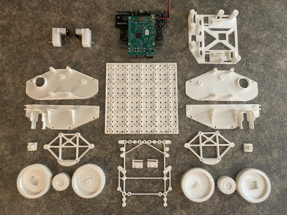
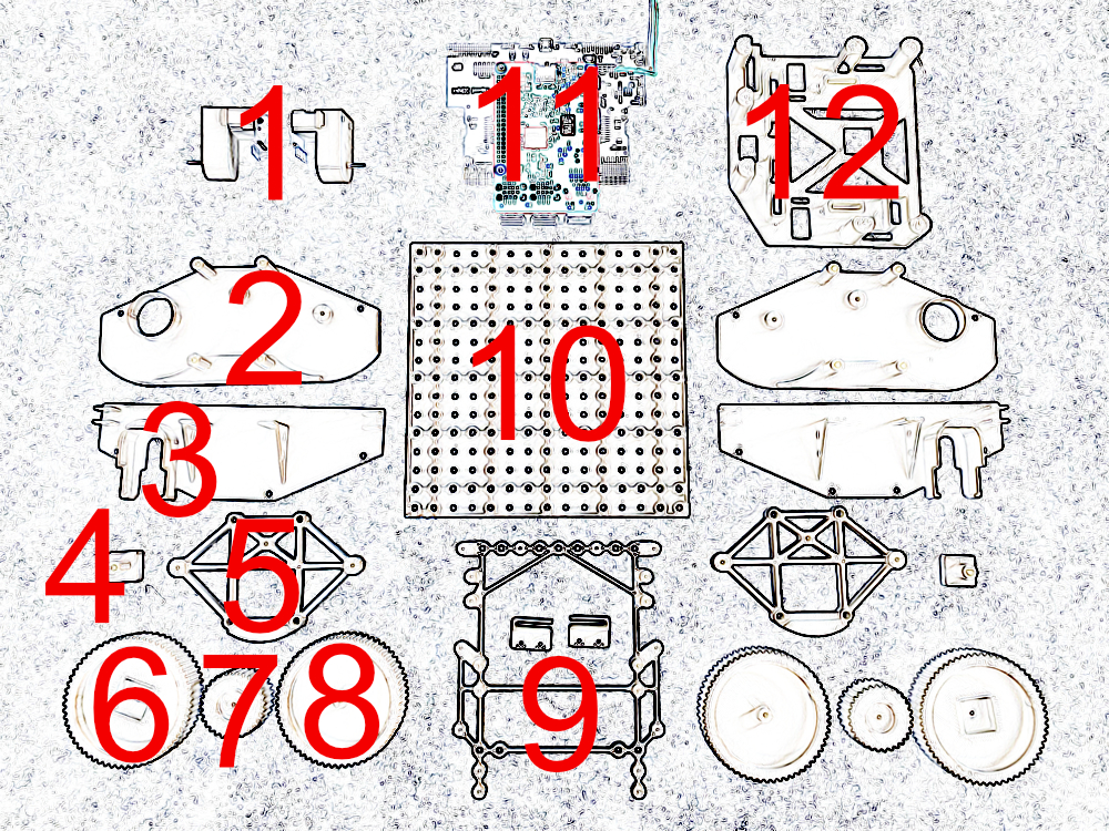
- Romi Motors
- Outer Wheel Frame
- Inner Wheel Frame
- Square Drive Post
- Wheel Frame Support
- Drive Wheel
- Transfer Gear
- Coast Wheel
- Romi Mount and Wire Holders
- Robot Base
- Romi and Pi
- Electronics Cover
To assemble the chassis, you must download and print these parts. Once the parts have been printed, you can start assembly. In addition to the printed parts you will need:
- 10cm jumper wires
- 3mm nuts and bolts
- Blue thread locker
- 2mm axel shafts
- M2 self-tapping screws
- Romi Control Board
- Two Romi Motors with Encoder
- Raspberry Pi
- PCB Male Header Pins
- PCB Jumper Cap
- Power Connectors
- 18650 Battery Holder
- 18650 Batteries
- Battery Charger
- Small rubber band
Links directly to individual products can be found in the TL;DR;
Want to save time? These specific parts were ordered for our robot, they may or may not be currently sold by Amazon.
When buying jumper wires, we recommend both 10cm and 20cm jumper wires. The 10cm wires work well for connecting the drive motors to the Romi board, however the longer jumper wires will work fine if you already have them and don't mind tying up the extra length. As you connect mechanisms to the top of the robot, having a collection of the longer 20cm jumper wires will be helpful.
While many robotics teams may have a large collection of small ANSI sized nuts and bolts, it is easier to find assortment packs of metric sized nuts and bolts. 3mm (also referred to as M3) is a very common size for small fasteners used in 3D printing projects, so KnightKrawler has opted to use this size for our primary fastener. Feel free to substitute fasteners of a comparable size that works for you. All of the parts are made to work with any pan head or cap head bolt. None of the parts in the current designs are designed to work with countersunk or V-set bolts.
Blue thread locker is a cheap and easy way to secure nuts onto bolts. However if you don't like thread locker because it is too messy or find it doesn't work well, you can purchase M3 nylon lock nuts.
The Romi board includes screws holes that are too small for M3 bolts. For this assembly, we use M2 screws. By using screws, It makes it possible to remove the electronics without disassembling significant parts of the robot. Be sure to purchase screws that are actual screws with a point, not machine screws that have bolt threads.
Check the Pololu Romi documentation. At the time of assembling these instructions, the supported models of Raspberry Pi were 3B+ and 4B. Our robots work with 3B+, which is also a lower cost model.
There are many options for powering your Romi. The Romi requires only 5-6V to power the boards and drive the robot. However, in testing we have found closer to 12v works better if you plan to control other mechanisms such as a shooter or pickup mechanism. Most servos require 5V and many small toy car motors require 6V-24V. KnightKrawler has opted to use three 18650 Lithium-Ion batteries. This provides about 12V of power when fully charged. In testing, we found that running a shooter motor and two servos at the same time was possible with 12V. However at 7-8V, the Raspberry Pi would "brown out" resulting in a reboot. The 18650 batteries provide flexibility for charging batteries in multi-bank chargers. You may also want to consider using battery packs made for RC cars. These battery packs come in a variety of shapes and voltage outputs and generally simplify charging.
There are many options for wire connectors to use for your wire to power your Romi and Raspberry Pi. If you plan to use RC Car Battery packs, select the connector type that will work with your battery packs. Otherwise, select a connector type balances size and ease of use when connecting and disconnecting your batteries.
Step 1: Side Mounting Frames
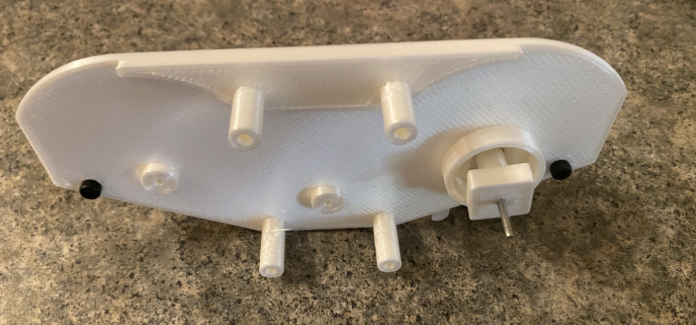
- Snap the motor into position on the inside mounting plate for the side
- Press the square drive peg, onto the motor shaft. See TL;DR; for tips on this step
- Place the outside mounting plate next to the inside mounting plate through the large round opening for the square drive peg
- Fasten the inside and outside mounting plates using only the two holes shown with M3 bolts that are at least 8mm long and either thread locker or nylock nuts
- Repeat this step so both left and right sides are assembled
If the square drive peg does not have a snug fit on the motor shaft, use a small piece of a rubber band to create a tight fit. Place the rubber band over the hole, then press shaft into the hole. Make sure to properly align the flat side of the shaft. Push the square drive peg on to the shaft so approximately 1-2mm of space remains between the motor and square drive peg. Trim the rubber band as short as possible after shaft is inserted.
When fastening the bolts on the chassis sides, always place the nuts so they will be under the robot body (towards the motor).
Depending on the settings of the 3D printer or filament being used, the motor may not be as secure as you desire. You can reduce motor movement with hot glue if desired.
Step 2: Wheels
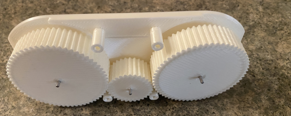
- Cut one 2mm axel shaft 12-14mm long
- Insert this shaft into the square drive peg and slide the drive wheel onto the shaft
- Cut two 2mm axel shafts 20-22mm long
- Insert these shafts through the transfer wheel and coast wheel
- Position the shafts of these two wheels into the mounting frame
- Place the side wheel frame over the 3 axel shafts
- Secure the top of the drive frame with M3 bolts at least 30mm long and the lower with M3 bolts at least 32mm long
- Use blue thread lock or nylock nuts on each bolt
- Repeat this step so both left and right sides are assembled
Axels can but cut a variety of different ways. A hacksaw with a vice is a solution many robotics teams may have. A more portable solution is to use a Lineman's Pliers. Additionally, cutting axels can leave a sharp end. To round the end to avoid cuts to your skin or snags inside the 3D printed parts, the ends can be sanded with metal sandpaper, or a sharpening stone.
Different print quality can impact the size of axel holes. Axels should slide easily into parts, and wheels should spin freely on the axel. It may be necessary to use a drill and small drill bit to enlarge holes if they are too snug.
If bolts are too long and extend too far into the body of the robot, it may impact mechanisms mounting on the base. You may decide to reverse the bolts, so the extra length of the bolt is towards the outside of the wheel frame, rather than extending into the robot body. Alternatively, the lineman's pliers can be used to trim the bolt length after the nuts are installed.
The geared wheels provide great traction on carpet but can slip on hard surfaces. The wheels are designed to allow for a custom track tread to be designed and 3D printed with extra soft TPE flexible Filament. Unfortunately, flex filament can be difficult or impossible to print on some 3D printers. A wide rubber band can be used as a substitute for a track.
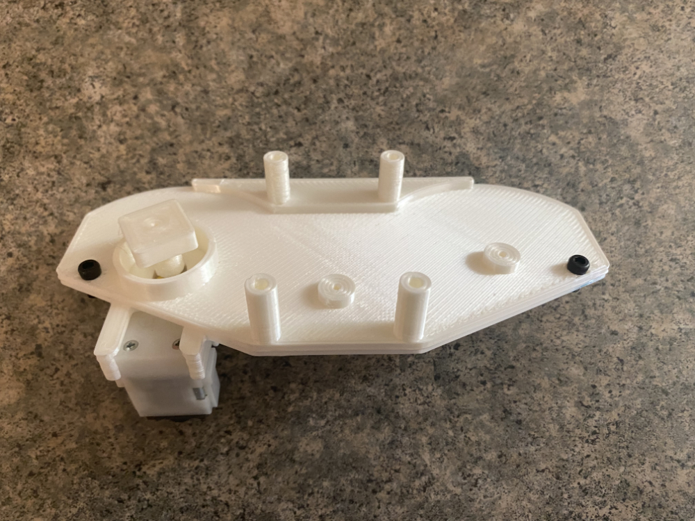
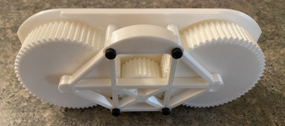
Step 3: Base
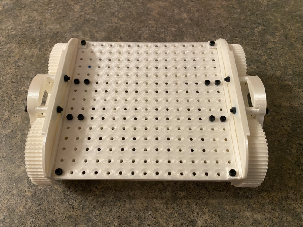
- Attach the wheel frame sides to the base using M3 12mm bolts or longer in the four corners
- Using eight M3 10mm or longer, attach the inner frame braces near the center along the sides
- Use blue thread lock or nylock nuts on each bolt
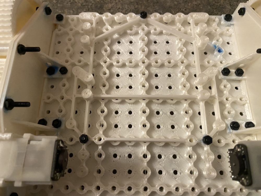
- On the underside of the frame, fasten the Romi mount so the mounting hole in the "V" is in the center out most row of mounting holes away from the motors
- Mounting posts for the Romi are taller than the rest of the frame to hold the board away from the base, these posts must be up (towards the Romi board) as shown in the photo
- Use three M3 12mm bolts to fasten the mounting frame to the base as show in the image
There are extra mounting holes available for the Romi mounting bracket in the event you create mechanisms that would require bolt heads to be in a different location.
Step 4: Soldering
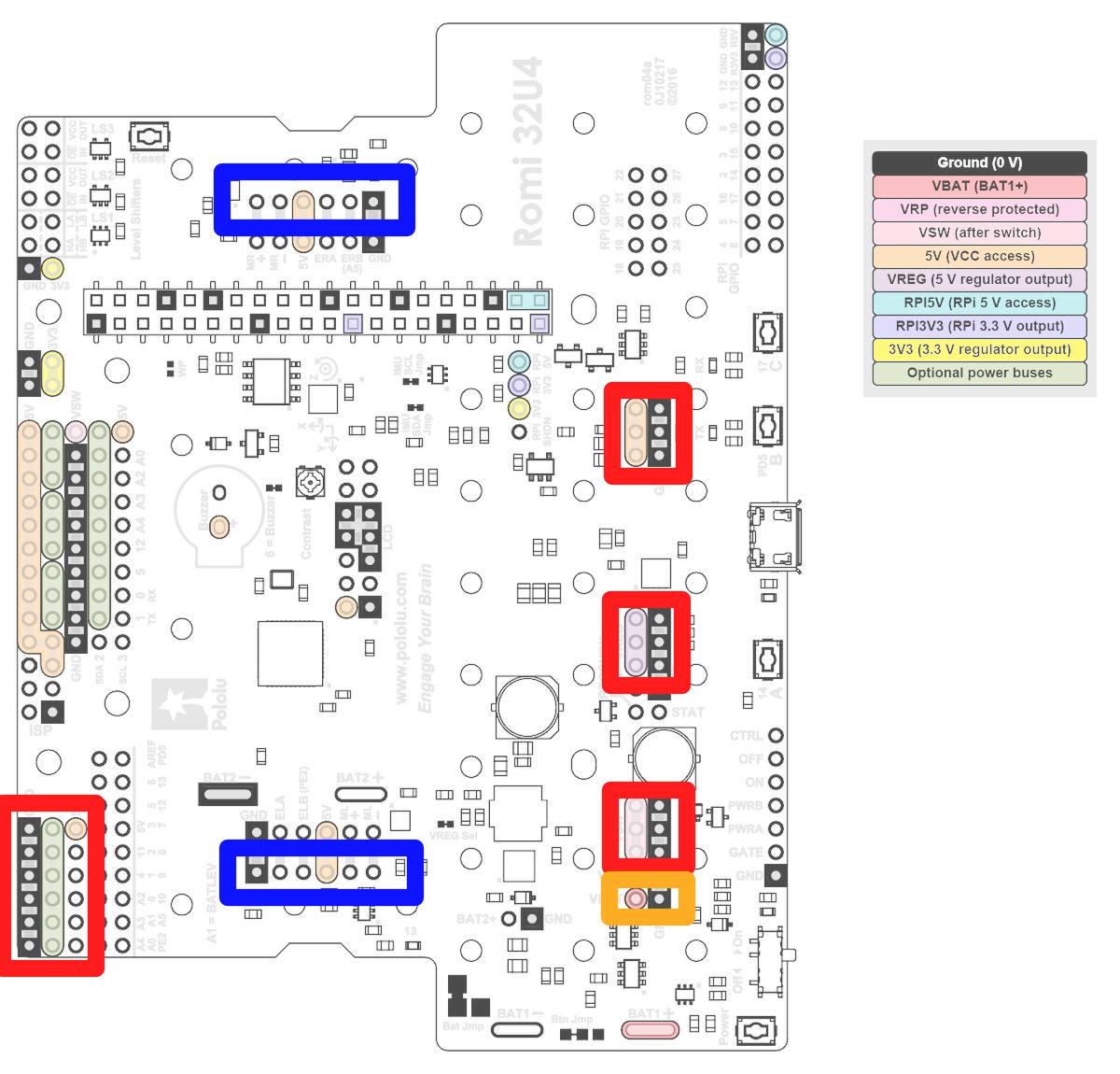
Original image source courtesy of Romi webpage
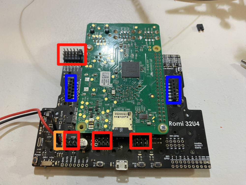
- The Romi board comes with 1x6 female pin headers for the motors. Solder those in place per the Romi instructions (shown in blue)
- Solder wires for the power leads to your battery connection - Power In (shown in orange)
- Solder three 2x3 male pin headers for positive and negative connections (shown in red)
- Solder 3 rows of male PWM pin headers (positive, negative, signal) (shown in red)
- See instructions for attaching option header jumper cap to PWM pins, as well as tips for soldering in the TD;DR;
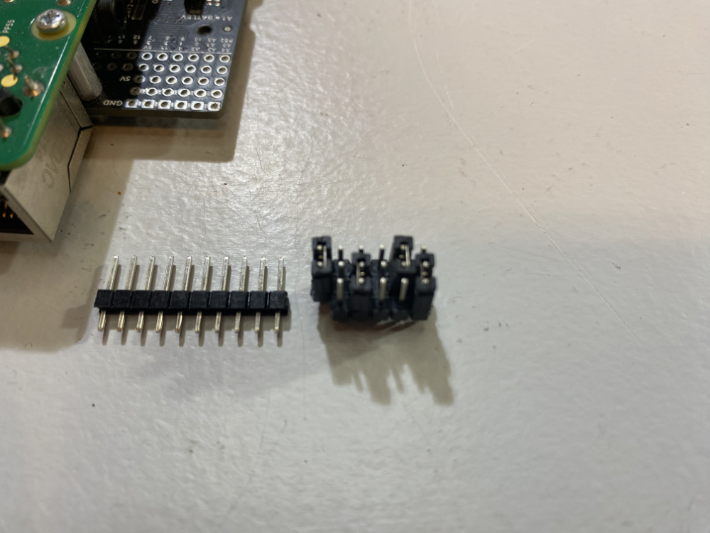
Pin headers come in long strips and can be snapped between the pins to obtain the desired pin header length. Pin header jumper caps are an easy way to hold multiple rows of pin headers together when soldering. In this photo, the pin headers for the PWM pins have been connected using 4 jumper caps.
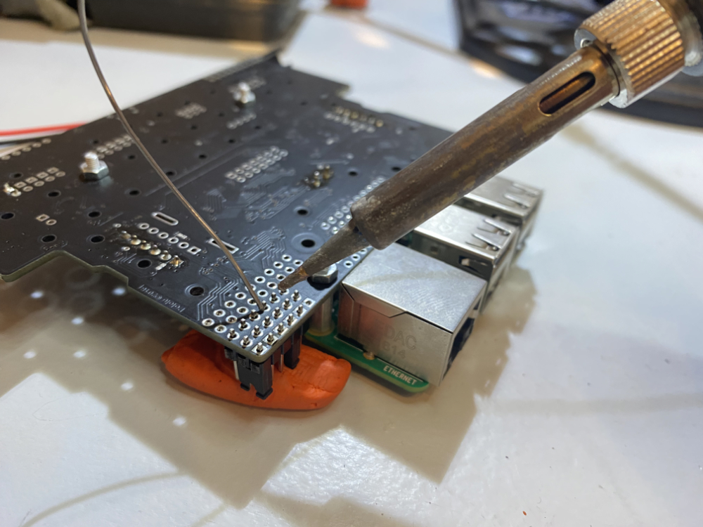
Modeling clay can be used to hold the pin headers in place while placed upside down on the Romi board. When soldering, do not place the solder on the tip of the soldering iron, but rather use the soldering iron to heat the pin and connector on the board. Touch the solder to the pin and board to complete the weld. Electronics solder include a material called flux, which cleans the connection. If solder is placed on the soldering iron, the flux does not do its job of cleaning the parts to be connected. Note: Some modeling clay may melt if too much heat is transferred through the pin into the clay. It may be necessary to use a toothbrush, or other bristle brush, to clean off the header pins if the clay melts to the pins.
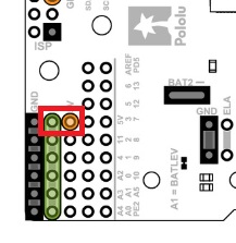
The Romi board includes a convenience strip of standard PWM connections for running additional motors or servos for future mechanisms. However the 5v power bus is not connected by default. Use a header jumper cap to connect the 5V pin adjacent to the signal pins, to the middle pins of the PWM connections.
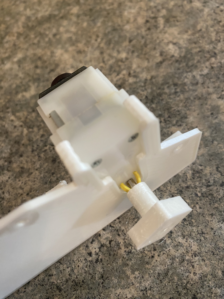
Step 5: Wiring
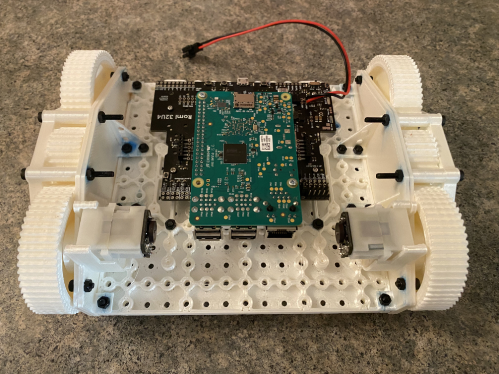
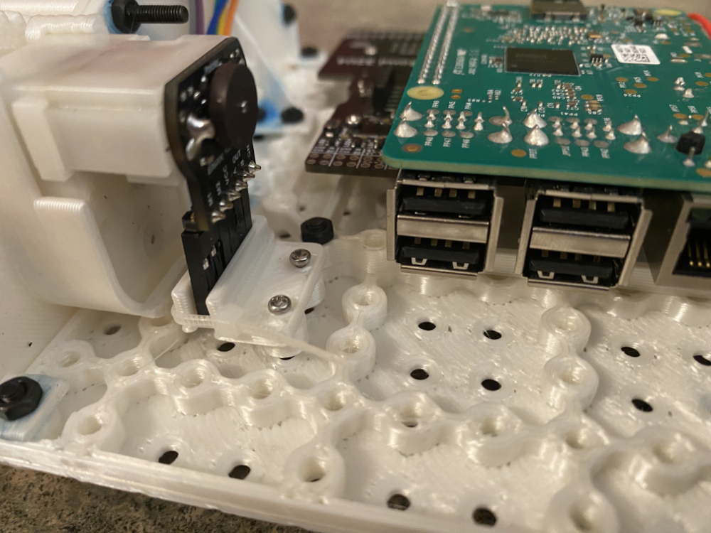
- Using M2 screws, attach the Romi board to the Romi mount
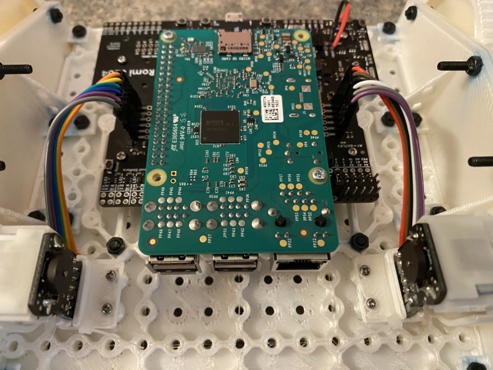
- Using 10cm (or 20cm) male-to-female jumper wires, attach the motors to the Romi board
- Using M2 screws, attach the retaining clips for the jumper wires to the Romi mount
- With a small zip tie, secure the clips around the wire ends
The Romi board should be secured to the Romi mount using screws not bolts. This allows for the board to be removed in the future, without requiring access to the top of the robot base part. The Romi mount includes 4 or 6 spots where a screw lines up with mounting holes on the Romi board.
Attaching the jumper wires requires patience and fine motor skills. 10cm jumper cables are just long enough to complete the connection. Start with the connection on the motor side. It may be easiest to connect the wires one at a time using a needle-nose plyers. Be sure to connect the wires in the same sequence (left to right) between the motor and Romi board.
Carefully slide the wire retention clips in place after the motor wires have been connected. Secure the clips to the Romi mount using M2 screws. With a small zip tie, clamp the clips to the wire ends.
Skipping Ahead: Code
Romi Subsystems are similar, but control mechanisms unlike those usually found on a real FRC robot. Currently, the Romi attempts to control PWM motor controllers that use a single locked-antiphase PWM signal. These motor controllers are often large and/or expensive. Low cost PWM motor controllers (also called an "H-Bridge") typically used on RC cars cannot use this signal. Instead they need an analog (voltage) signal for forward, and a second signal for reverse. Unfortunately, the Romi does not allow for analog out. So the only option is a Digital Out signal. This is effectively either 0% or 100% voltage.
The TL;DR; includes 3 complete subsystem classes for the intake, shooter, and indexer. Copy these classes to avoid needing to figure out how control servos and H-Bridge motor controllers from scratch. You may need to modify the package name to match your project.
    package frc.robot.subsystems;

    import edu.wpi.first.wpilibj2.command.SubsystemBase;
    import edu.wpi.first.wpilibj.Servo;

    public class IndexerSubSystem extends SubsystemBase {
        private static IndexerSubSystem instance = null;
        private Servo hopperGateServo;
        private Servo shooterGateServo;

        public void openHopperGate() {
            hopperGateServo.setAngle(0);
        }

        public void closeHopperGate() {
            hopperGateServo.setAngle(90);
        }

        public void openShooterGate() {
            shooterGateServo.setAngle(0);
        }

        public void closeShooterGate() {
            shooterGateServo.setAngle(90);
        }

        public static IndexerSubSystem getInstance() {
            if (instance == null)
            {
            instance = new IndexerSubSystem();
            }
            return instance;
        }
        /** Creates a new IntakeMotor. */
        private IndexerSubSystem() {
            hopperGateServo = new Servo(3);
            shooterGateServo = new Servo(2);
            closeHopperGate();
            closeShooterGate();
        }
    }
    package frc.robot.subsystems;

    import edu.wpi.first.wpilibj.DigitalOutput;
    import edu.wpi.first.wpilibj2.command.SubsystemBase;

    public class HBridgeIntakeSubsystem extends SubsystemBase {

        private static HBridgeIntakeSubsystem instance = null;

        public static HBridgeIntakeSubsystem getInstance() {
        if (instance == null)
        {
            instance = new HBridgeIntakeSubsystem();
        }
        return instance;
        }

        private HBridgeIntakeSubsystem() {}

        private DigitalOutput pinForward = new DigitalOutput(8);

        private boolean pinFOut = false;

        public void IntakeIn()
        {
        pinFOut = true;
        }

        public void Stop()
        {
        pinFOut = false;
        }

        @Override
        public void periodic() {
        // This method will be called once per scheduler run
        pinForward.set(pinFOut);
        }
    }
    package frc.robot.subsystems;

    import edu.wpi.first.wpilibj.DigitalOutput;
    import edu.wpi.first.wpilibj2.command.SubsystemBase;

    public class HBridgeShooterSubsystem extends SubsystemBase {

        private static HBridgeShooterSubsystem instance = null;

        public static HBridgeShooterSubsystem getInstance() {
        if (instance == null)
        {
            instance = new HBridgeShooterSubsystem();
        }
        return instance;
        }

        private HBridgeShooterSubsystem() {}

        private DigitalOutput pinForward = new DigitalOutput(9);

        private boolean pinFOut = false;

        public void ShooterForward()
        {
        pinFOut = true;
        }

        public void Stop()
        {
        pinFOut = false;
        }

        @Override
        public void periodic() {
        // This method will be called once per scheduler run
        pinForward.set(pinFOut);
        }
    }