LEDs the KnightKrawler Way
After a few years of failed attempts at LEDs, including a few rounds of magic smoke and burned-out controllers, KnightKrawler set off to create a uniform way to control LEDs. The goal was to create a setup that would work the same on the robot, or at a desk. We wanted a way to have several "training setups" that worked identical to the way it would work on the robot connected to a RoboRio. This resulted in a few concrete design guidelines.
WS2812b LEDs
We decided to standardize on WS2812b LEDs. These LEDs are 5 volts and low power consumption.
More importantly, they are low cost and easy to find.
This type of LEDs also opened up the opportunity to created additional LED projects, such as
an LED display panel for the robot cart, or wearable LEDs for hats and vests.
Using 12V automotive LEDs often found on FRC robots would have made these other projects
more complicated or impossible. We alos decided to purchase LEDs enclosed with a waterproof
rubber sleeve. While the waterproof part isn't necessary, the rubble sleeve protects against
accidental shorts and offers some protection to the strip.
ESP32 Co-processor
While many teams are using an Arduino for LED control. The very limited processing power
and memory, coupled with price of Arduino processors was a bad combination.
The ESP32 chips run the same Ardunio code.
and there are many ESP32 platforms for under $10 which offer significantly more power and
memory in a much smaller package.
Easy and Safe Power
We wanted the co-processor to always be run from USB power. It is possible to directly power
a co-processor from a battery, since most chips have a VIN (Voltage In) pin.
While correct wiring practices will ensure that this can be done safely, there is always the
possibility that a cheap ESP32 manufacturer or a mistake in wiring could send reverse
voltage back
into laptop. Your $10 LED processor could severely damage your very expensive computer. To
reduct this risk, we decided to ensure the ESP32 co-processor is always powered off USB.
This creates
the need for a powered USB plug. However, but adding this plug is makes a training setup
very simple for students to understand. They can plug the ESP32 into the computer to program
it, when doing so
the processor is powered by the laptop. Then unplugging the processor from the laptop and
into the USB power source on the training setup, puts the chip on the independent power
source. Our training
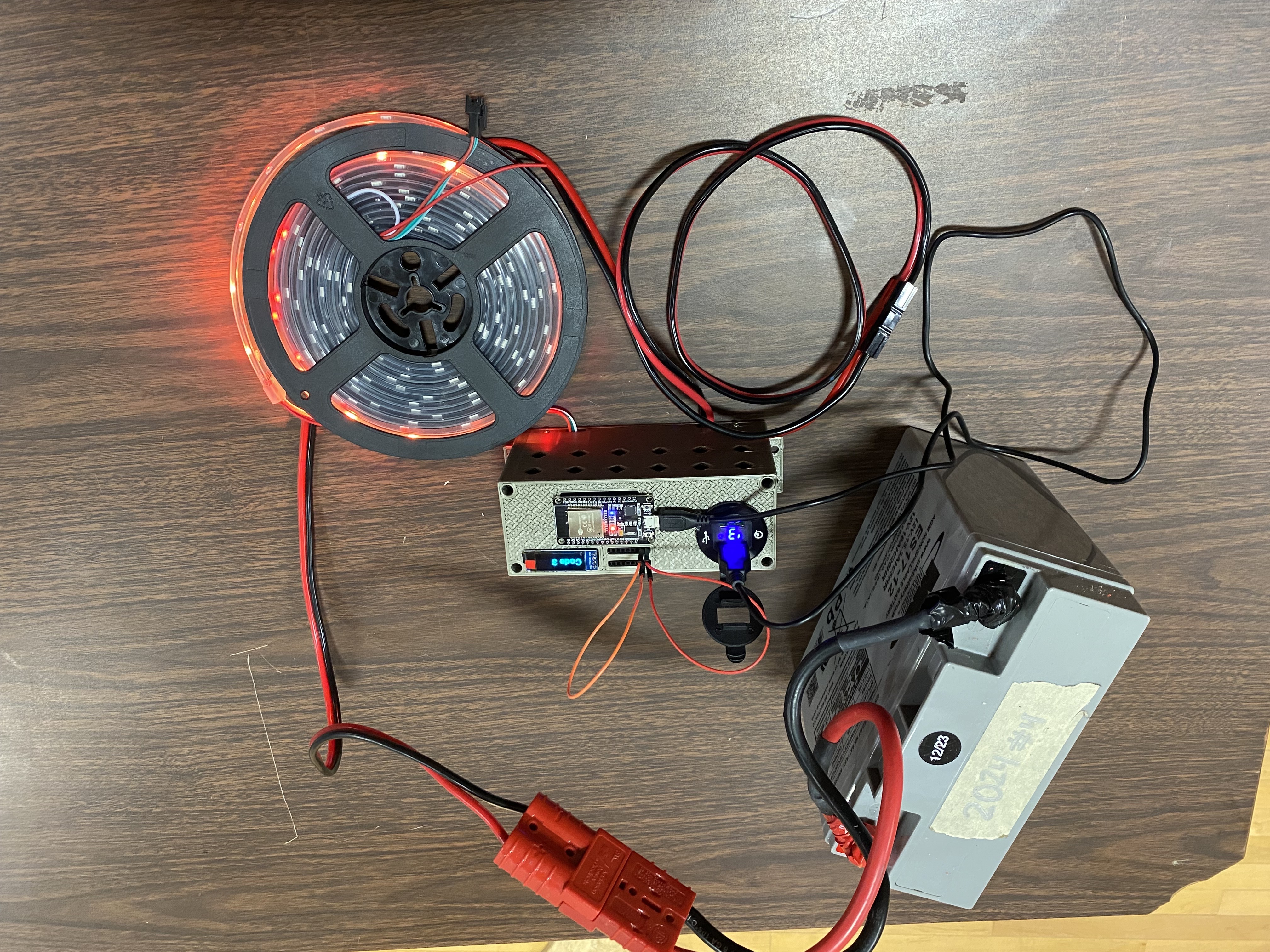
setup runs on a 12v robot battery. For training, a student simply grabs a robot battery,
sets it on the desk, and the entire system is ready to go. This also makes it possible for
the same setup to
be used for lights on the pit, robot cart, or anywhere you want to display LEDs.
Easy to Troubleshoot Signaling
Communicating between the RoboRio and a co-processor can be a challenge for any team to figure out,
especially new teams. Worse, it can become near impossible to troubleshoot more complicated computer
protocols such as SPI or I2C if you are not an expert and choose to communicate to your
co-processor this way. Adding to the complexity, how do you simulate a call from the RoboRio
to change the light pattern if you are communicating over SPI or I2C if you don't have
a RoboRio? So, KnightKrawler uses a very simple approach to changing the light pattern. We
use binary signals and DIO. This will be explained in detail later, but using simple HIGH or
LOW pin voltages,
(similar to a DIO sensor such as a limit switch), allows for troubleshooting with simple
debug statements or even a voltage meter. Each pin on the co-processor can represent a
binary number.
If pins 0,2,and 3 are being signaled, this would represent the binary number 1011 or the
number 13 (1 + 4 + 8) in decimal. Very few teams are using all 10 DIO pins on their Robio.
Having just 5 of the 10 pins
available means you have 2^5 (32) different light patterns you can code. Adding a screen to
your processor makes debugging even easier.
Female Pin Sockets
The diagram indicates two pin socket strips will be used. These are only necessary if you plan to create a test box (below).
It is possible to use jumper wires directly from the pins on the ESP32 co-processor board directly to ground for testing.
For connecting to the RoboRio, these pins can be wired directly to the RoboRio DIO pins through a ribbon cable or jumper wires.
We assume you will want at least a couple LED of setups so you can have one on the robot, and more for testing. Some parts are as cheap to buy in bulk as they are to buy 1. Here is the list of parts we purchase.
- ESP32 Processor
- 12v to 5v Power Converter
- USB Charger Socket
- OLED Display
- Female Header Socket
- Male Header Pins
- WS2812B Waterproof LED Strip
- Lever Wire Connectors
- Jumper Wires
- PCB Boards (optional)
You will need wire and a connection to your robot battery. KnightKrawler uses the Anderson connector for our batteries. It is wise to separate the resting setup from the battery with Anderson Powerpole connectors. By doing this, it is possible to connect your testing rig directly to the PDH on the robot more easily.
Common Ground
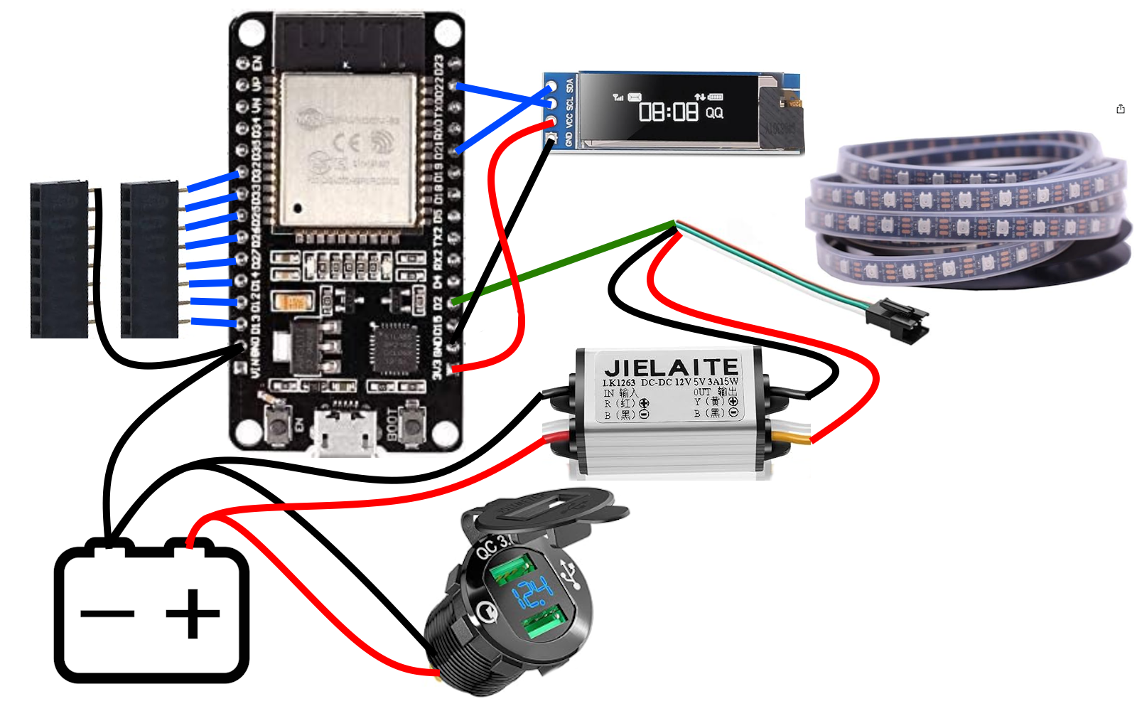
A common mistake in wiring and working with a co-processor is establishing a common ground. When the co-processor is connected to a laptop, it receives its
positive and negative power connection through the USB cable to the laptop. However, we cannot power the LEDs off the power that comes from the USB port.
There just isn't enough power, so power is supplied through the robot battery. The ESP32 processor is attempting to control the LEDs through a signal wire
connected to pin 2 in the diagram above. A problem is created when the co-processor is powered from the laptop, and the LEDs are powered by the battery.
There must be "common ground". Notice in the diagram that the ESP32 has a ground connection to the battery that powers the LEDs. If your LED lights flicker erratically,
you are probably missing a common ground.
DIO Input
In the diagram. The female header sockets for DIO input is connected on pins D13, D12, D14, D27, D26, D25, D33, and D32. The pin order may seem illogical and we agree. Different manufacturers will use different
pin numbering. This diagram uses the Upesy Wroom DevKit linked in the shopping list. We have also used the more expensive HiLetgo
board with integrated screen, which has a very different pin numbering scheme. However, we have noticed a delay in the screen and do recommend this co-processor if you want very quick light
changes for your robot.
Pull-Up
There is a concept in circuitry called a "Pull-Up Resistor" or "Pull-Up Circuit". In electricity, when attempting to read a DIO signal, you really need to have a HIGH (3.3V) signal or a LOW (0V - Ground) signal.
This can be an abstract concept to first grasp and there a many YouTube videos explaining this. In practice with a pin is not connected to anything at all, it is "floating", which means it could read either
HIGH or LOW and can fluctuate depending on static in the air and a variety of other things. Pull-up circuits allow a pin to read high when nothing is connected. Nearly all boards including the RoboRio and ESP32 include
the ability to tell a pin to turn on the build in pull-up resister. Some boards have the option for pull-down circuits but it is less widely supported and therefore not a reliable way to write code. Unfortunately, this means
when we write code we have to assume with a pin reads high the circuit is open (off) and when it reads low it is closed (on). To make this work, we have to connect the other set of female header pins to ground. It seems
backwards to the person new to electronics, so for now just trust this is the easiest way to make this system work.
Screens
There are many shapes, sized and styles of screens. We have chosen this screen for cost and compact size. Most screens have a simple I2C connection using the "CL" (clock) and "DA" (data) pins. It makes
programming a display easy. Make sure your display is powered from the 3V output on the co-processor, not 5V pin.
Power
We selected a low cost 12V to 5V converter for powering the LEDs and a simple USB power socket. More robust converters are available they my tolerate brown-outs more gracefully, but we have not encountered an issue so far.
The converter for the LEDs can supply up to 3 amps. If you are attempting to run multiple strips or panels you may need a converter that can supply more amps.
On the standard LED wire harness, white is ground (negative), green is signal, and red is power (positive).
Pins
Selecting pins to use in wiring your lights can vary. The diagram only shows the pins we have used for DIO input, and for signaling the LEDs (pin 2). A word of caution, verify the input pins support "Pull-Up" mode in
your code before soldering anything. We found that not all pins on the Upesy Wroom kit support the pull-up feature.
Models
Download the models from Printables.com
Circuit Board
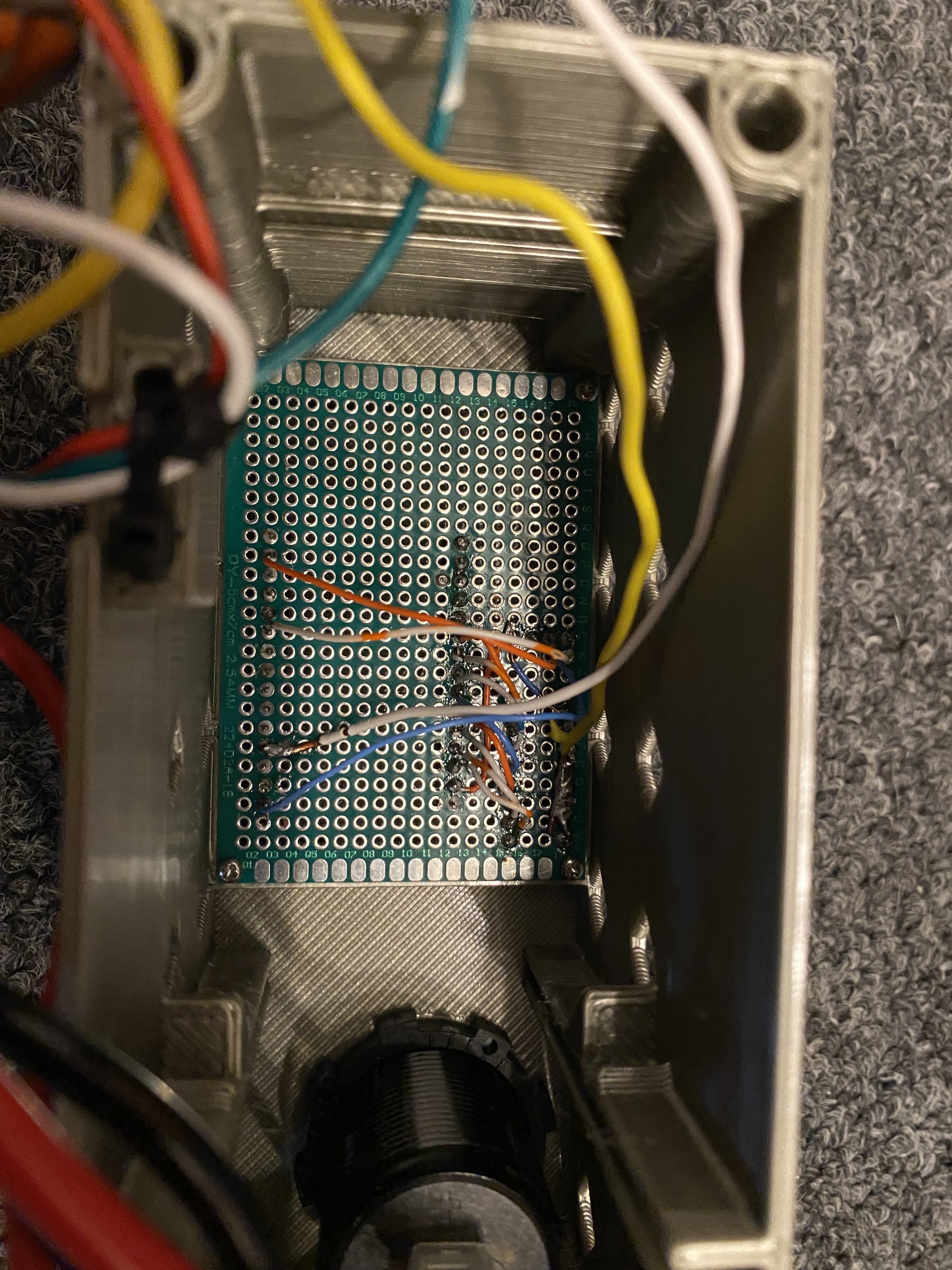
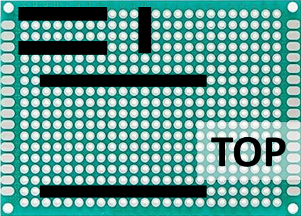
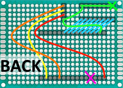
To create the KnightKrawler training setup using the 3D printed case above, a 18x24 PCB board and female pin sockets are needed. The diagram above shows the position of the female pin headers on the circuit board (top side). Female pin headers can be cut to the desired number of pins using a side cutter or any snips you have available. Sandpaper can be used to create a nice flat end to your cut female pin headers. From the back side, solder the female pin headers into the board and connect each pin as shown in the diagram using your preferred soldering method. In the photo shown, wires from a CAT-5 cable were used to connect the pins. You may prefer a different way to create your PCB. In the diagram, a green "X" indicates a ground wire is needed to attach to the battery negative lead (common ground). A pink "X" indicates a lead wire is needed to connect to the signal for the LED strip. These wires should be about 6" long. See the diagram above under the "Wiring" header to see how they are connected to the other components.
NOTE: the soldering diagram is only viable when using the Upesy Wroom Dev kit ESP32 board. You may need to adjust the soldering pattern to fit the pins on your micro processor board.
Secure the PCB board to the 3D printed case using small screws. We used 2mm screws in our assembly. Depending on your 3D printer nozzle and layer settings, the fit may be snug and can take some wiggling to get in place. If the openings are too small in the corners it may be necessary to sand them open with small strips of sand paper, or to remove some plastic using an exacto knife.
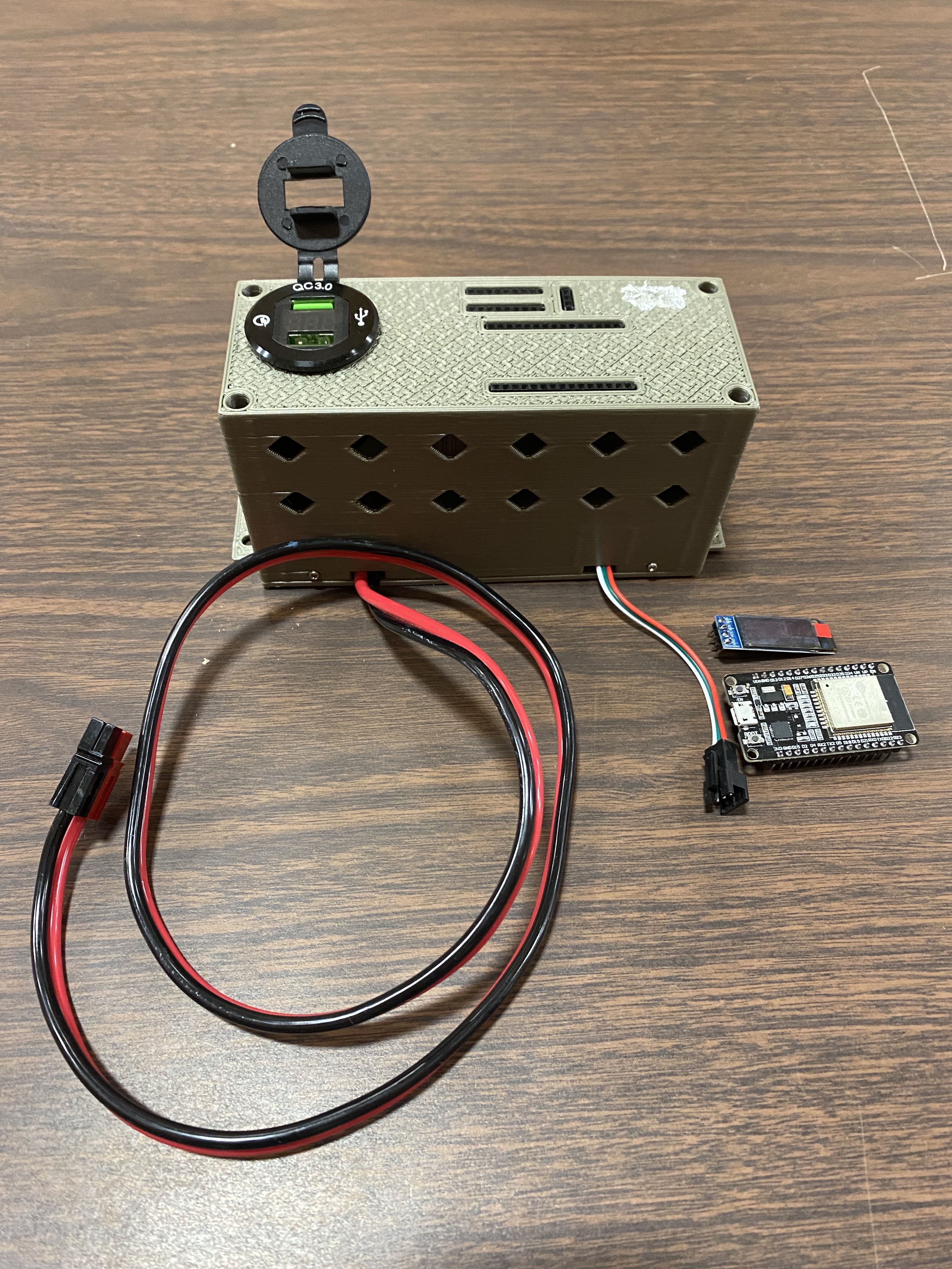
Assembly
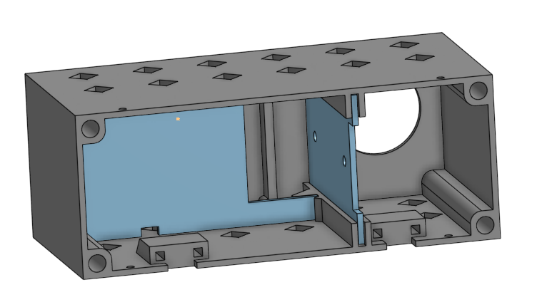
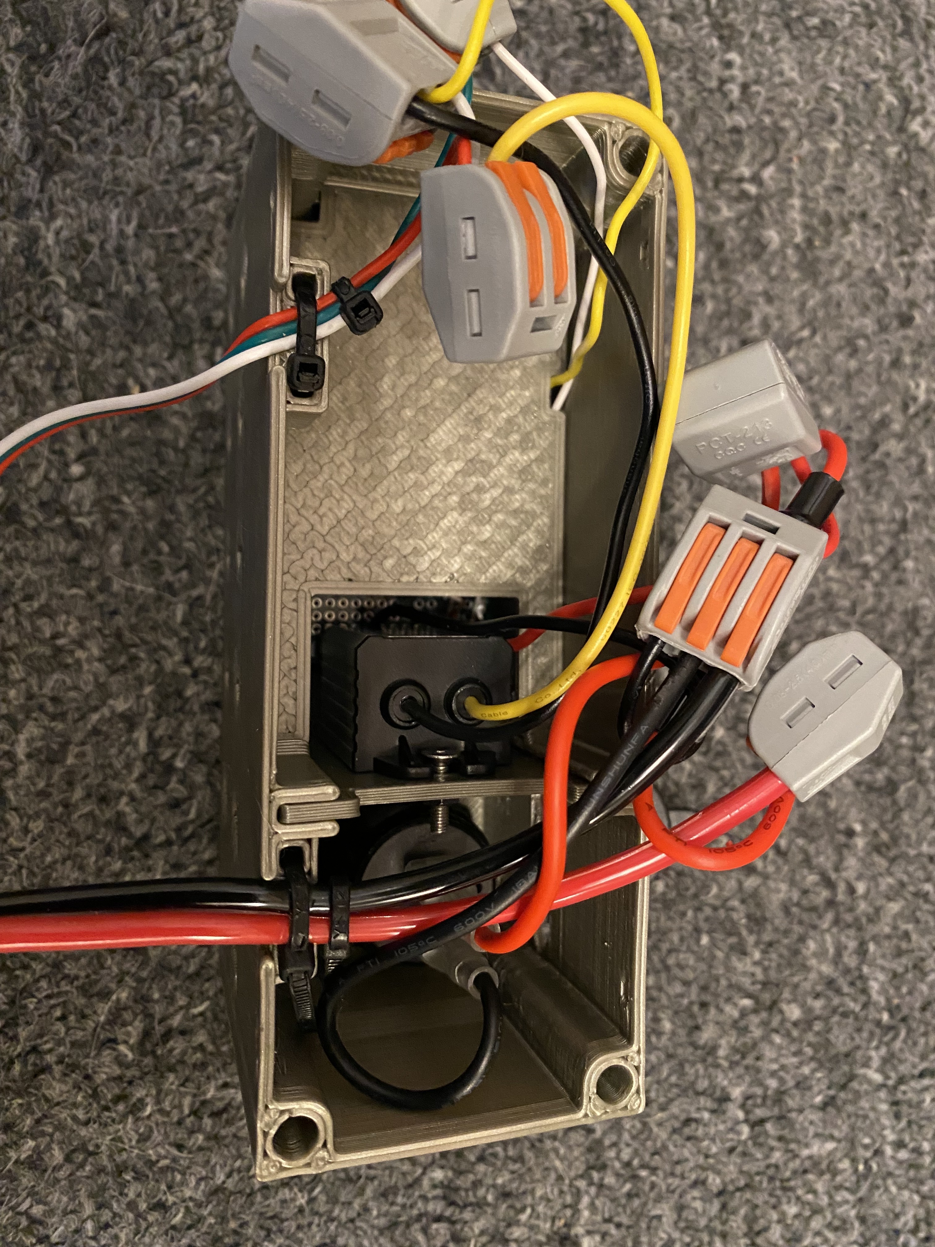
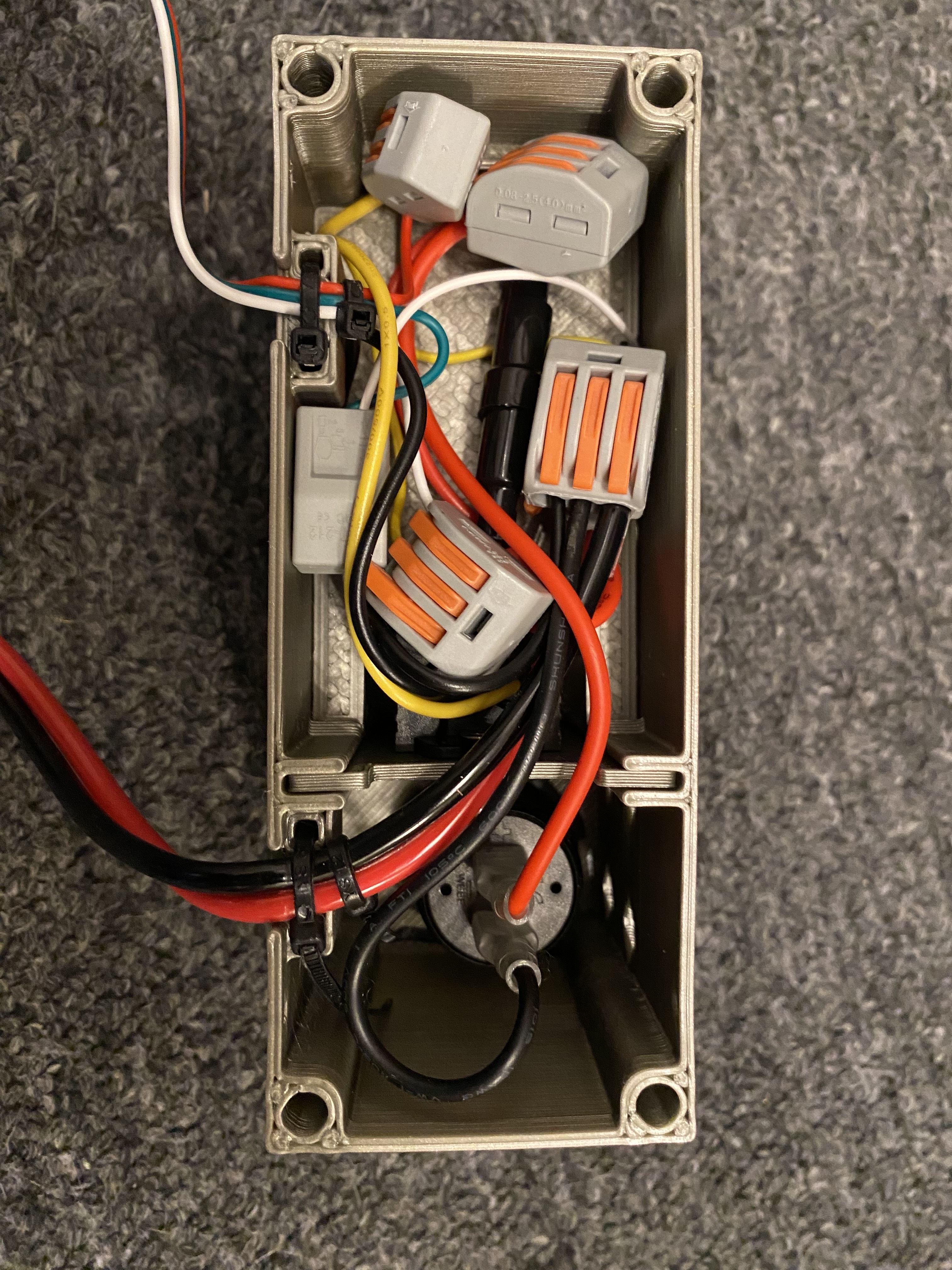
There are two dividers that go inside the case. One snaps in to protect the solder connections on the PCB board from any power wires that could break a solder connection. The other divider is a mount for the 12v to 5v converter we recommend. Use small screws to secure the PCB Board to the case, as well as the bottom of the case. 2mm diameter screws work well. Insert the circular USB socket in the round hole and attach the 12v to 5v convert to vertical divider using small nuts and bolts (3mm) and slide into place. Connect all wires following the wiring diagram above using lever nuts and organize the wires inside the case. Use small zip ties to secure wires for the battery power and LED lights. Secure the back of the case to the main body, again using small 2mm screws.
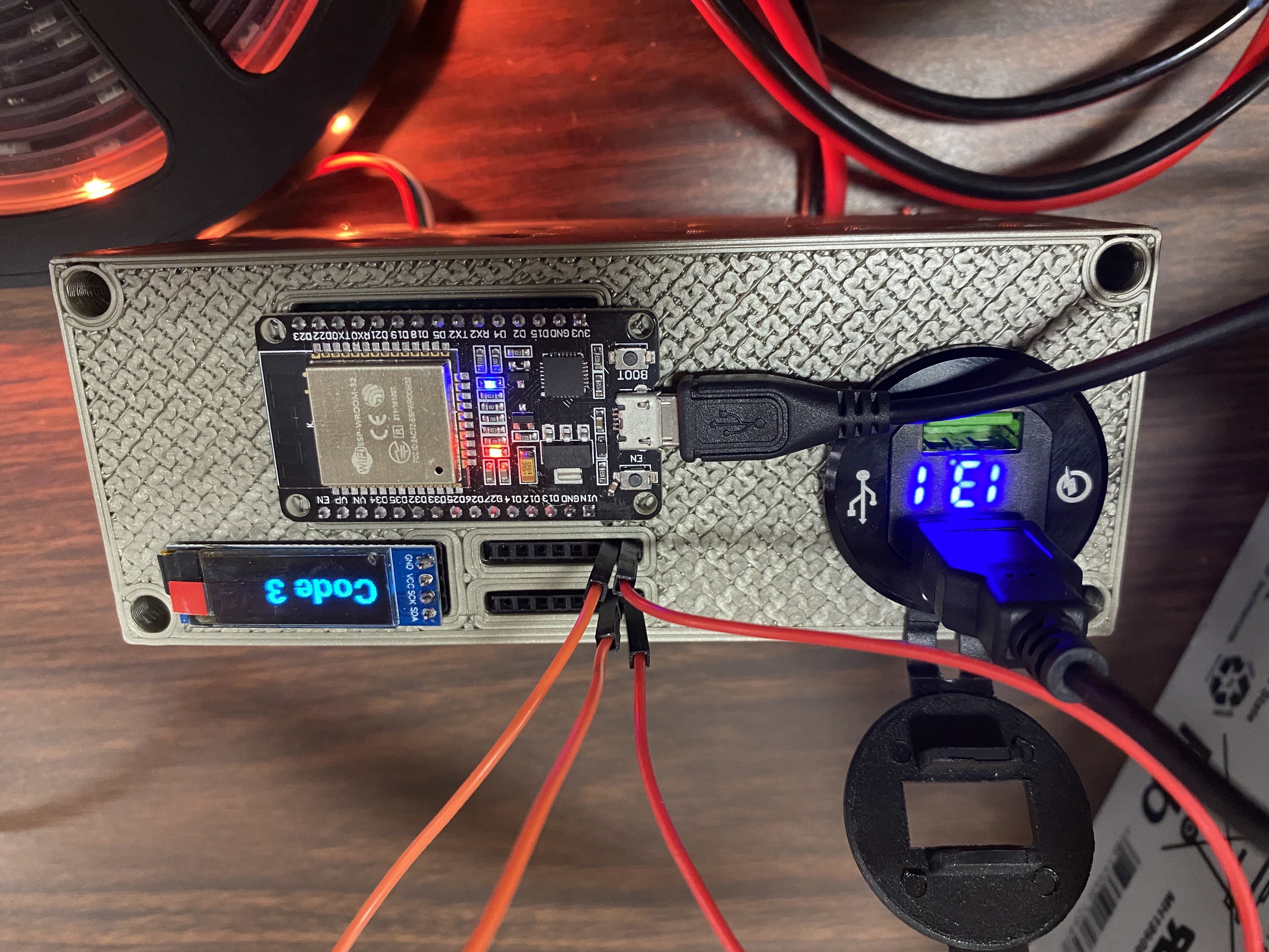
Once fully assembled, a USB cable will be used to power the micro processor from the USB ports. Jumper wires will be used to bridge the header sockets to test input that will eventually come from the RoboRio.
For reasons stated in the "Goals" section of this page, KnightKrawler uses a very simple approach to changing the light pattern. We use binary signals and DIO. Eash pin represents a bit in a byte (1+2+4+8+16+32+64+128). While this gives you the option of 256 light patterns, in practice you are unlikely to need more than 4 or 5 pins (16-32 patterns). This approach makes it easy for a student to use jumper wires to connect the pins on the ESP32 to a ground connection, closing the circuit to represent a number the ESP32 code can read. If you passed over the "Pull-Up" section of the wiring description, go back and read that now.
Bellow is example Java code used by KnightKrawler during the 2024 season. This code is part of the robot code that runs on the RoboRio
    package frc.robot.subsystems;

    import edu.wpi.first.wpilibj.DigitalOutput;
    import edu.wpi.first.wpilibj.DriverStation;
    import edu.wpi.first.wpilibj2.command.SubsystemBase;
    import frc.robot.Constants;
    import frc.robot.RobotState;
    import frc.robot.auto.AutoFactory.Auto;
    import frc.robot.util.io.Dashboard;

    /**
     * Subsystem to control the robot's LEDs, by determining what number should be encoded to DIO pins and
     * sent to the Arduino we used for controlling the patterns and colors
     */
    public class LedSubsystem extends SubsystemBase {
        private static LedSubsystem INSTANCE;

        private final DigitalOutput codeChannel1, codeChannel2, codeChannel3, codeChannel4;

        private LEDStatusMode currentStatusMode;

        private boolean disablePeriodicEval = false;

        private LedSubsystem() {
            // DIO outputs
            codeChannel1 = new DigitalOutput(Constants.LEDs.CHANNEL_1_PIN);
            codeChannel2 = new DigitalOutput(Constants.LEDs.CHANNEL_2_PIN);
            codeChannel3 = new DigitalOutput(Constants.LEDs.CHANNEL_3_PIN);
            codeChannel4 = new DigitalOutput(Constants.LEDs.CHANNEL_4_PIN);

            currentStatusMode = LEDStatusMode.OFF;
        }

        public static LedSubsystem getInstance() {  // Method to allow calling this class and getting the single instance from anywhere, creating the instance if the first time.
            if (INSTANCE == null) {
                INSTANCE = new LedSubsystem();
            }
            return INSTANCE;
        }

        public static enum LEDStatusMode {
            OFF(0),
            DANGER(1),
            INTAKE(2),
            HAS_NOTE(3),
            AIMING(4),
            AIMING_ON_TARGET(5),
            SHOOTING(6),
            SHOOTING_ON_TARGET(7),
            DONE_SHOOTING(8),
            NO_AUTO(9),
            BLUE_AUTO(10),
            RED_AUTO(11),
            AMP_IDLE(12);

            private final int code;

            private LEDStatusMode(int code) {
                this.code = code;
            }
        }

        @Override
        public void periodic() {
            if(!disablePeriodicEval) {

                // robot disabled

                if (DriverStation.isDisabled()) {
                    // If disabled, gets the alliance color from the driver station and pulses that. Only pulses color if connected to station or FMS, else pulses default disabled color (Firefl status mode)
                    Auto selected = Dashboard.getInstance().getAuto();
                    if (selected == Auto.NO_AUTO || selected == null){
                        currentStatusMode = LEDStatusMode.NO_AUTO;
                    } else if (RobotState.getInstance().isRedAlliance()) {
                        currentStatusMode = LEDStatusMode.RED_AUTO;
                    } else if (!RobotState.getInstance().isRedAlliance()) {
                       currentStatusMode = LEDStatusMode.BLUE_AUTO;
                    } else {
                        currentStatusMode = LEDStatusMode.OFF; // Reaches here if DriverStation.getAlliance returns Invalid, which just means it can't determine our alliance and we do cool default effect
                    }

                // autonomous LED status modes

                } else if (DriverStation.isAutonomous()) {
                    if(RobotState.getInstance().getNoteHeldDetected()){
                        currentStatusMode = LEDStatusMode.HAS_NOTE;
                    } else if (RobotState.getInstance().getIsShamperAtGoalAngle()){
                        // currentStatusMode = LEDStatusMode.AIMING;
                    } else {
                        if (RobotState.getInstance().isRedAlliance()) {
                            currentStatusMode = LEDStatusMode.RED_AUTO;
                        } else if (!RobotState.getInstance().isRedAlliance()) {
                            currentStatusMode = LEDStatusMode.BLUE_AUTO;
                        }
                    }
                }

                // teleop LED status modes

                if (DriverStation.isTeleopEnabled()) {
                    // shooting
                    if(RobotState.getInstance().getShooting()){
                        if(!RobotState.getInstance().getNoteHeldDetected()){
                            currentStatusMode = LEDStatusMode.DANGER;
                                            } else if (RobotState.getInstance().getNoteHeldDetected() && RobotState.getInstance().getIsShamperAtGoalAngle() && RobotState.getInstance().getIsRotationOnTarget()){
                            currentStatusMode = LEDStatusMode.SHOOTING_ON_TARGET;
                        } else {
                            currentStatusMode = LEDStatusMode.SHOOTING;
                        }
                    }
                    //  aimed
                    else if (RobotState.getInstance().getNoteHeldDetected() && RobotState.getInstance().getIsShamperAtGoalAngle() && RobotState.getInstance().getIsRotationOnTarget()){
                        currentStatusMode = LEDStatusMode.AIMING_ON_TARGET;
                    }
                    // aiming
                    else if (RobotState.getInstance().getIsVerticalAiming() || RobotState.getInstance().getIsHorizontalAiming())
                    {
                        currentStatusMode = LEDStatusMode.AIMING;
                    } else if (RobotState.getInstance().getAmpIdle()){
                        currentStatusMode = LEDStatusMode.AMP_IDLE;
                    }
                    else {
                        if(RobotState.getInstance().getNoteHeldDetected()){
                            currentStatusMode = LEDStatusMode.HAS_NOTE;
                        } else if (RobotState.getInstance().getIsIntaking()){
                            currentStatusMode = LEDStatusMode.INTAKE;
                        } else {
                            currentStatusMode = LEDStatusMode.OFF;
                        }
                    }
                }
            }

            int code = currentStatusMode.code;

            // Code for encoding the code to binary on the digitalOutput pins
            Dashboard.getInstance().putData("Sending LED Code", code);
            codeChannel1.set((code & 1) > 0);   // 2^0
            codeChannel2.set((code & 2) > 0);   // 2^1
            codeChannel3.set((code & 4) > 0);   // 2^2
            codeChannel4.set((code & 8) > 0);   // 2^3
            // codeChannel5.set((code & 16) > 0);  // 2^4
        }

        public void setLEDStatusMode(LEDStatusMode statusMode) {
            if (!disablePeriodicEval) {
                currentStatusMode = statusMode;
            }
        }

        public LEDStatusMode getLEDStatusMode(){
            return currentStatusMode;
        }

        public void clearStatusMode() {
            currentStatusMode = LEDStatusMode.OFF;
        }

        // Disables LEDs (turns them off)
        public void disableLEDs() {
            disablePeriodicEval = true;
        }

        // Enables LEDs (turns them on)
        public void enableLEDs() {
            disablePeriodicEval = false;
        }
    }
The Ardiuno Code will be explained in greater detail in a future update to this page. Until then we recommend viewing Platform.IO and LED tutorials by Dave's Garage on YouTube
You can also find our Arduino LED code on GitHub: https://github.com/frc2052/2024RobotLEDs